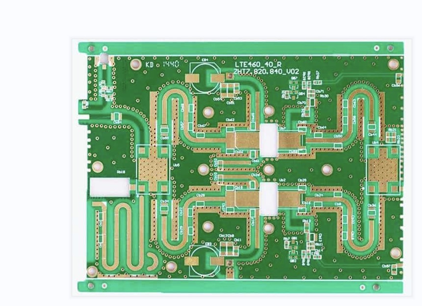
What is A Microwave & RF PCB?
A microwave & RF PCB is a PCB that works at signal frequencies between megahertz and gigahertz (between medium frequency to extremely high frequency). These boards are used in communication devices such as wireless networks, satellite broadcasters, cell phones, and radar stations.
How Do RF and Microwave PCBs Work?
Unlike traditional digital circuit boards, RF and microwave signals are much more sensitive to noise, and they require tighter impedance tolerances. To minimize these issues, RF microwave PCBs utilize ground plans and generous bend radius on impedance controlled traces.
What are the Materials to Use for RF Microwave PCB?
RF Microwave PCBs are fabricated using advanced composites with very specific characteristics for dielectric constant (Er), loss tangent, and co-efficient of thermal expansion (CTE). These high frequency circuit materials allow for a significant reduction in impedance compared to standard FR-4 material. They can also be mixed together in the same stack-up for optimal performance and economics.
What Are the Most Common Problems With RF and Microwave PCBs?
The most common problems with RF and microwave PCBs are signal reflection, ringing, and signal noise. These problems are primarily caused by return losses. To reduce this issue, RF microwave PCBs need to be designed with multiple power planes. These power planes can be spaced across the edge of the board to avoid return loss.
What Is the Process to Make a Microwave PCB?
The process of making a Microwave PCB is quite complex, and requires specialized tech and materials. Typically, this type of board is only made by manufacturers that specialize in these types of electronics.
What are the Advantages of Microwave & RF PCB?
The main advantages of microwave & RF PCBs are a broad frequency range, excellent performance, and specialized technology. They can be used for a wide variety of applications and have become popular in recent years.
1. Relative Permittivity: The relative permittivity of substrate materials is a function of frequency that determines the behavior of electric fields passing through the material. This property is particularly important for RF/Microwave circuit boards where a low dielectric permittivity can decrease parasitic capacitance between conductive structures and copper traces and improve overall electrical performance.
2. High-Dk Materials: Many microwave circuits involve several passive components such as filters, couplers and impedance tuning structures. These components often require a higher Dk material to operate at a specific wavelength.
3. Lower CTE: These materials have a low coefficient of thermal expansion (CTE) which makes them easier for a PCB engineer to align numerous layers of boards into intricate patterns and reduce assembly costs.
4. Anti-Radiation: When RF/Microwave circuits are used in space or nuclear applications, the substrate material must be resistant to the massive ionizing radiation. This requires the use of special coatings which can protect the materials from the damaging effects of radiation.
5. The sensitivity of RF/Microwave Signals: The RF and microwave signals are much more sensitive than digital ones, and they must be treated with care to minimize noise, ringing, and reflection.
A good RF/Microwave circuit design includes careful planning of routing to maximize return loss. This can include the creation of ground planes underneath signals to minimize radiated power from any source that might disrupt signal transmission.
Why Do Industries Need Microwave PCB and RF PCB?
Many industries, especially the medical and automotive sectors, need RF and microwave PCB to make their products effective and durable. The demands of these industries are high and it is necessary for them to manufacture reliable products that comply with the set manufacturing standards.
Developing a Quality Product
Creating a high-quality RF or microwave PCB requires careful planning, including accurate substrate material determination, reasonable and scientific electrical characteristics modification, and other significant aspects of layout design. This will ensure that you are able to produce reliable end products.
The layouts of RF and microwave circuits are more complex than that of conventional circuits, due to the distributed parameters nature of the designs. This makes it difficult to control skin and coupling effects. Additionally, the electromagnetic radiation in the circuits can cause interference and cross-talk issues.
Choosing the Right Transmission Lines
The choice of transmission lines for a RF PCB design can be challenging, but it can also be important for the overall performance of the board. Coplanar waveguides are a great option to isolate RF signal lines and reduce losses.
Choosing the Right Material
When designing an RF or microwave PCB, it’s essential to choose a material that meets all your needs for electrical performance and thermal robustness. It’s also important to select a material that will work with your specific application and budget.
PTFE, for example, is an engineered thermoplastic fluoropolymer that offers excellent dielectric properties for RF and microwave applications. Moreover, this material has low resistive losses at microwave frequencies. Other popular RF materials include Megtron 6 and PTFE laminate reinforced with woven glass.
What are the Factors Affecting RF PCB & Microwave PCB?
RF and microwave circuits are highly sensitive to noise, reflection, and ringing. They are also prone to EMI interference, making them more difficult to design than typical analog or digital PCBs.
The sensitivity of these signals requires that the design team carefully mitigate any potential interference or high-frequency noises that can occur. Fortunately, there are a number of methods that can be used to minimize the effects of these sources, such as band pass filters and decoupling capacitors.
Impedance Matching & Traces
RF transmission lines require strict impedance matching to ensure that signal power is not lost. This is particularly important for microstrips, striplines and coplanar waveguides (grounded), all of which require characteristic impedance values. These are typically 50O or 75O, based on the width of the trace and the thickness of the layer.
Materials
Unlike conventional PCBs, RF PCBs require certain materials that meet specific requirements for electrical performance and thermal properties. The material must have low signal losses, be stable over high-frequency operation, and can absorb a significant amount of heat to dissipate it.
Via Design
The placement and size of vias can have a dramatic impact on electrical performance. It is crucial to place vias in the correct position, and not directly on RF traces.
Ground Planing
A ground plane is an essential part of the RF PCB and helps reduce its overall dimensions and improve performance by providing thermal and electrical paths for heat flow away from components like transistors or amplifiers. It can be made from a variety of materials, but copper is ideal as it has good conductivity and helps increase efficiency.
Ava Mitchell
Ava Mitchell is a digital culture journalist at Explosion.com covering social media platforms, streaming services, and the creator economy. With 4 years reporting on TikTok, Instagram, YouTube, and the apps that shape daily life, Ava specializes in explaining platform policy changes and their impact on everyday users. She previously managed social media strategy for a tech startup, giving her firsthand experience with the platforms she now covers.